ADT7488A
http://onsemi.com
10
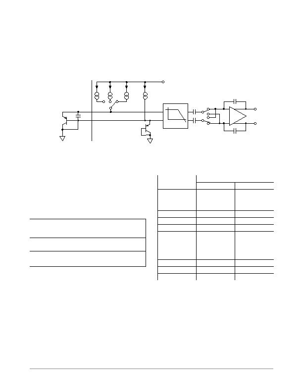
current I. The currents through the temperature diode are
switched between I and N1 ?I, giving DV
BE1
, and then
between I and N2 ?I, giving DV
BE2
. The temperature can
then be calculated using the two DV
BE
measurements. This
method can also cancel the effect of series resistance on the
temperature measurement. The resulting DV
BE
waveforms
are passed through a 65 kHz low-pass filter to remove noise
and then through a chopper-stabilized amplifier to amplify
and rectify the waveform, producing a dc voltage
proportional to DV
BE
. The ADC digitizes this voltage, and
a temperature measurement is produced. To reduce the
effects of noise, digital filtering is performed by averaging
the results of 16 measurement cycles for low conversion
rates. Signal conditioning and measurement of the internal
temperature sensor is performed in the same manner.
Figure 15. Signal Conditioning for Remote Diode Temperature Sensors
LOW-PASS FILTER
f
C
= 65 kHz
REMOTE
SENSING
TRANSISTOR
BIAS
DIODE
D1+
D1
V
CC
I
BIAS
I
N2 ?I
V
OUT+
V
OUT
To ADC
C1*
*CAPACITOR C1 IS OPTIONAL. IT SHOULD ONLY BE USED IN NOISY ENVIRONMENTS.
N1 ?I
Reading Temperature Measurements
The temperature data returned is two bytes in little endian
format, that is, LSB before MSB. All temperatures can be
read together by using Command Code 0x00 with a read
length of 0x06. The command codes and returned data are
described in Table 14.
Table 14. TEMPERATURE CHANNEL COMMAND
CODES
Temp
Channel
Command
Code
Returned Data
Internal
0x00
LSB, MSB
External 1
0x01
LSB, MSB
External 2
0x02
LSB, MSB
All Temps
0x00
Internal LSB, Internal MSB;
External 1 LSB, External 1 MSB,
External 2 LSB, External 2 MSB
SST Temperature Sensor Data Format
The data for temperature is structured to allow values in
the range of ?12癈 to be reported. Thus, the temperature
sensor format uses a twos complement, 16-bit binary value
to represent values in this range. This format allows
temperatures to be represented with approximately a
0.016癈 resolution.
Table 15. SST TEMPERATURE DATA FORMAT
Temperature (5C)
Twos Complement
LSB
MSB
125
1110 0000
1100 0000
80
1110 1100
0000 0000
40
1111 0110
0000 0000
20
1111 1011
0011 1110
5
1111 1110
1100 0000
1
1111 1111
1100 0000
0
0000 0000
0000 0000
+1
0000 0000
0100 0000
+5
0000 0001
0100 0000
+20
0000 0100
1100 0010
+40
0000 1010
0000 0000
+80
0001 0100
0000 0000
+125
0001 1111
0100 0000
Using Discrete Transistors
If a discrete transistor is used, the collector is not grounded
and should be linked to the base. If a PNP transistor is used,
the base is connected to the D input and the emitter is
发布紧急采购,3分钟左右您将得到回复。
相关PDF资料
ADT7518ARQZ
IC SENSOR TEMP QD ADC/DAC 16QSOP
AT30TS00-MAH-T
SENSOR DGTL TEMP I2C/SMBUS 8WDFN
AT30TSE002B-MAH-T
SENSOR DGTL TEMP I2C/SMBUS 8WDFN
BD3504FVM-TR
IC REG CTRLR SGL POS ADJ 8MSOP
BD3521FVM-TR
IC REG CTRLR SGL 1.5V MSOP8
BD9153MUV-E2
IC REG TRPL BCK/LINEAR 24VQFN
CAT2300VP2-GT3
IC SENSE FET CONTROLLER 8TDFN
CAT34TS02VP2GT4A
IC TEMP SENSOR 2K MEMORY 8TDFN
相关代理商/技术参数
ADT7488AARMZ-RL7
功能描述:板上安装温度传感器 TMP SNSR/VLTG MON W/SST INTERFACE RoHS:否 制造商:Omron Electronics 输出类型:Digital 配置: 准确性:+/- 1.5 C, +/- 3 C 温度阈值: 数字输出 - 总线接口:2-Wire, I2C, SMBus 电源电压-最大:5.5 V 电源电压-最小:4.5 V 最大工作温度:+ 50 C 最小工作温度:0 C 关闭: 安装风格: 封装 / 箱体: 设备功能:Temperature and Humidity Sensor
ADT7490
制造商:AD 制造商全称:Analog Devices 功能描述:dBCool Remote Thermal Monitor and Fan Controller with PECI Interface
ADT7490ARQZ
功能描述:马达/运动/点火控制器和驱动器 FAN CTRLR W PECI INT RoHS:否 制造商:STMicroelectronics 产品:Stepper Motor Controllers / Drivers 类型:2 Phase Stepper Motor Driver 工作电源电压:8 V to 45 V 电源电流:0.5 mA 工作温度:- 25 C to + 125 C 安装风格:SMD/SMT 封装 / 箱体:HTSSOP-28 封装:Tube
ADT7490ARQZ-R7
功能描述:马达/运动/点火控制器和驱动器 FAN CNTRL W/PECI INT RoHS:否 制造商:STMicroelectronics 产品:Stepper Motor Controllers / Drivers 类型:2 Phase Stepper Motor Driver 工作电源电压:8 V to 45 V 电源电流:0.5 mA 工作温度:- 25 C to + 125 C 安装风格:SMD/SMT 封装 / 箱体:HTSSOP-28 封装:Tube
ADT7490ARQZ-REEL
功能描述:马达/运动/点火控制器和驱动器 FAN CNTRL W/PECI INT RoHS:否 制造商:STMicroelectronics 产品:Stepper Motor Controllers / Drivers 类型:2 Phase Stepper Motor Driver 工作电源电压:8 V to 45 V 电源电流:0.5 mA 工作温度:- 25 C to + 125 C 安装风格:SMD/SMT 封装 / 箱体:HTSSOP-28 封装:Tube
ADT7490ARQZ-REEL7
功能描述:IC THERM MON FAN CTRLR 24-QSOP RoHS:是 类别:集成电路 (IC) >> PMIC - 热管理 系列:dBCool® 标准包装:1 系列:- 功能:温度监控系统(传感器) 传感器类型:内部和外部 感应温度:-40°C ~ 125°C,外部传感器 精确度:±2.5°C 本地(最大值),±5°C 远程(最大值) 拓扑:ADC,比较器,寄存器库 输出类型:2 线 SMBus? 输出警报:无 输出风扇:无 电源电压:2.7 V ~ 5.5 V 工作温度:-40°C ~ 125°C 安装类型:表面贴装 封装/外壳:SOT-23-8 供应商设备封装:SOT-23-8 包装:Digi-Reel® 其它名称:296-22675-6
ADT7490ZEVB
功能描述:BOARD EVALUATION FOR ADT7490 RoHS:是 类别:编程器,开发系统 >> 过时/停产零件编号 系列:dBCool® 标准包装:1 系列:- 传感器类型:CMOS 成像,彩色(RGB) 传感范围:WVGA 接口:I²C 灵敏度:60 fps 电源电压:5.7 V ~ 6.3 V 嵌入式:否 已供物品:成像器板 已用 IC / 零件:KAC-00401 相关产品:4H2099-ND - SENSOR IMAGE WVGA COLOR 48-PQFP4H2094-ND - SENSOR IMAGE WVGA MONO 48-PQFP
ADT75
制造商:AD 制造商全称:Analog Devices 功能描述:+-1∑C Accurate, 12-Bit Digital Temperature Sensor
